
Phased and Agile development program methodologies can be used together effectively, meeting objectives of each, by managing synchronization between them and using continuous planning.
Published concurrently on www.softtoyssoftware.com.
Phased Development Sequence
The system development programs I’ve Program Managed developed both hardware and software. The hardware development uses Phased methodology, and software may use Agile methodology including a Program Increment (PI) roadmap. In fact, Partners, Supply Chain, Manufacturing, and suppliers may use different methodologies too. A system program needs to get most effective use from all of them.
Is Phased development Waterfall? In a common description of Waterfall methodology, the program sequence is perceived as a series of sequential tasks, executed serially, uni-directionally, and inflexibly. There is perceived emphasis on documentation. Waterfall sequencing is shown just below:

I don’t know if anybody really develops programs in the manner attributed to this simplistic view of Waterfall methodology! There’s enough competition now, so that things move faster and smarter. To differentiate what I’ve seen at multiple companies, from Waterfall methodology as I see it described nowadays, I use the term “Phased Development” to describe the development efforts I’ve Program Managed. Not sure if this is a deeper description of Waterfall, or a variant.
SDLC To hear all the rhetoric about Agile, you’d think that there are two choices: Waterfall (which is ponderous, inflexible, old-school, and horrible), or Agile (which reflects humanism and is wonderful). Unfortunately, Agile methodologies don’t well-support technologies that involve materials, partners, organizations, specialties, dependencies, durations and quantification. The real world, and real products, may require some of those. But the choice given is a “false choice” logical fallacy, and fortunately those are not the only two possibilities! So use or adapt Agile methodologies where appropriate to Program technology and organizational constraints. Otherwise, use or adapt other methodologies supporting those constraints, maintaining an Agile Mindset embodied by adaptability and timeliness.
Actually, there are “standard” methodologies derived from SDLC (“Software Development Life Cycle”) that are more flexible than basic Waterfall and include others with varying degrees of wonderfulness up to and including Agile. In this article, methodology will be described that supports co-existence of Agile with hardware methodologies for System development in a common Program. Then 6-Quantified Agile for Hardware, describes extension of Agile methodologies deeper into hardware development while concurrently honoring the quantifications needed for hardware development.
SDLC (ISO/IEC 12207; “Software Development Lifecycle” – please read this Tutorial!) starts by defining the basic SDLC stages (Planning, Defining, Designing, Building, Testing, Deployment). Then the methodology further defines SDLC Models followed in industry (Waterfall, Iterative, Spiral, V, Big Bang, Agile, RAD and Prototype). These vary in greater to lesser degrees of management, simplicity, flexibility, parallelism, incremental-ism, sequentiality, risk, coordination, product complexity and the like. These can be adapted to best-support organizational reality and technology of the product to be developed. For a particular example, in each of the SDLC Models some or all of the work “branches” that include “design-code-integrate-test” steps, might be replaced with Sprint cycles.
The methodology described throughout this series of articles supports SDLC stages, and further invokes elements of Iterative and Spiral SDLC methodologies with quantification to support multiple development methodologies for multiple technologies, as is common in systems. The resulting structure particularly supports system development involving multiple software modules (Agile, real-time decisions) and hardware modules (parallel, iterative, planned and real-time, quantified) to be developed, integrated, and productized as a system.
Phases are used to manage Depth and Breadth of Program development of the product, over the duration of the Program. First, Depth: A bunch of parallel tracks advance in parallel as the system product is developed. Development sequences include: Hardware EE, ME, FPGA et al – Design, function, robustness, reliability, compliance, international, for Boards, Assemblies, Systems; Firmware and Test – bringup, firmware control of electronics, firmware function, Diags, Mfg Test, Compliance test, online test; Software – boot, HW Management, kernel, retro function, new platform function, system and application management, certification, SQA test dev and execution, DevOps; Manufacturing – Onshore board build and test, assembly build and test, system delivery, Offshore CM, order forecast and processing; Supply Chain – local suppliers, BOM, alternate suppliers, offshore supplier volume; Analyst – training, support; CE – training, international spares. The detail goes much deeper than I’m describing here.
Then, Breadth: As these tracks progress, distribution widens to more systems, more uses, more locations. Breadth is provisioned by new builds, each at the current state along all Depth tracks, to build and distribute the most robust and functional systems, and to take advantage of improving unit cost.
Phases are organized around the builds, synchronizing states along the development depth tracks, so that units built meet current dependencies across all tracks, each Phase purposed to further advance specific development along each track. A Phase could contain several builds, targeted to particular uses. The Phases each contain build steps, materials and fabs, and PI or equivalent, and all activities along each track needed to further develop its intended purpose. Phases could also be defined that are centered around sync points that don’t contain a build.
Tasks in each Phase begin as soon they’re able (materials, personnel, and dependencies available), resulting in significant parallelism within and among Phases. A Program will reach a point where it’s simultaneously building prototypes for one Phase, while completing long-running tests on a prior Phase and purchasing (pre-fetching?) material for the next Phase. Nobody wants to wait (well, if they do, that’s why Program Managers wear pointy shoes). Note there are technical dependencies that control sequencing across Phases – some tasks are irreversible such as commitment of material, or environmental exposure, and such a task won’t start until its dependencies assure that the Program won’t regret that commit. Even formal reviews of Business- and Development-Commit occur in parallel with early development – we just make sure they’re done before significant spending occurs.
The Phase analog to a PI Program Board, is the program Schedule and material plan, which expresses tasks, dependencies, and provisioning, and includes their durations and dates. When I say “Schedule” I mean a task plan, with durations and dates; not just a list of dates. The derived dates are essential, to plan and execute hardware material handling, builds, spending and tests, because those are long duration, involve spending, and may involve partners. You must frequently plan backward, to months ahead of need date. Dates are also important to determine Critical Path of the program. Critical Path (task sequence with zero slack, that leads to FCS or other endpoints) is designed for parallelism, and managed to ensure progress, guiding task and sequence adjustments to maintain dates for quarterly spending, customer FCS and financial return. Use of dates for hardware development is directly related to connection of revenue to product delivery, and management of expenses required to get to that point. The revenue-on-product-delivery business model thus defined, is driven by the combination of Market Advantage, competitive landscape, Program return, and component lifecycle.
All Phases are planned out at the start of the Program, covering the life of the Program out to FCS (First Customer Ship, initiating Revenue flow), not limited to just an upcoming Phase. Phases aren’t increments to an evolving capability – instead, they are steps toward defined objectives for FCS date and Program return. Plans cover Phase overlaps, and material because of lead times, and quarterly Spend; all driven by task and material sequences. And we need a plan for how to achieve the Program FCS date.
For hardware development, Phase schedule and logistics are planned to the best extent possible and are updated and evolved throughout the duration of the Program. Any part of the plan may be at a high level if that’s all we know, but gets deeper over time. This isn’t accomplished over a few days – it’s a concerted effort throughout the life of the Program. Schedule (planned task sequence) drives Logistics (materials and other expense and cap items), and Logistics drives Finance (budget, reviews, and actuals). Material and build sequences, and long-running tests, dominate hardware development schedule after the initial design work; and history for these is available from prior program plans. Most design work after the initial effort overlaps with the build and test tasks. If we encounter a problem big enough to cause delay, we try to take it off the critical path to solve, and then re-integrate the solution back into the plan thus preserving the critical path.
That’s not all true for software elements. Software below a virtualization level, tied closely to hardware function, test, and management, does have to synchronize with the Phase plan for hardware. But above the virtualization level, Agile PI methodology may be imposed to avoid all this. (Except that, in my experience 80% of Program hardware built is to support development of those software elements so there remains a loose connection after all.) Predictability varies across software effort, from design work, SQA and end-game; to incorporation of existing function and libraries from various sources, integration steps, and certification. I schedule key points to build that 80% of hardware. Software, even using PI methodology, must provide functionality synchronized to needs by other organizations; and meet the System FCS date without regression. This applies especially to software intended to exploit characteristics of the system platform.
Planning less-well-definable work is synthesized by estimating task sequencing and duration, with particular focus on function integration sequences, using expertise and history. Planning is at a high-level if that’s all we got. The plan is iterated initially to attempt to fit to anticipated business objectives – organizations won’t maintain the program if it doesn’t meet return objectives.
That plan may seem inaccurate. But plans are refined continually as the program progresses, so plan and reality do converge better than you may expect. More than that, as the program develops, tasks may be modified to fit committed Program objectives; or those objectives may be modified. The plan is also an essential tool to plan and manage change. Due diligence is required, but answers may reasonably span a range – all plan components act to determine the “best-known-path from here”. The organization gets pretty good at this. Continuous planning also records, validates, refines and updates task sequencing and duration estimates. These guide work to accomplish Program objectives; to update the objectives themselves; and provide history for planning subsequent programs.
So that’s the methodology. How does that look on a Program?
Hardware Phased Workflow, shown with relation to perceived Waterfall
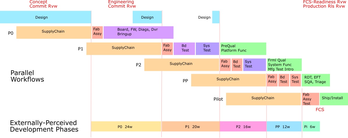
Much of the parallelism of Phased development is invisible to most of the organization, because it’s distributed among all organizations. As shown at the bottom of the figure just above, the period from start of build of one revision, to start of the next revision build, is pretty visible and is what’s perceived as the sequential Waterfall tasks. The line at the bottom of the figure shows that mapping, and maybe illustrates the confusion about Waterfall methodology. There’s a lot going on before and after – the ducks are paddling like crazy beneath the surface. And it’s mostly up the the Program Manager to keep them in a row.
In the figure just below, as in the figure above, horizontal bars show task sequences implementing an “Integration Cycle” in each Phase. These are long-duration sequences that build, integrate, and test Elements, function, and processes that implement the product of the Program. Each Integration Cycle includes a Prototype Cycle to build, and a Qual Cycle to validate processes and product configurations that it implements.
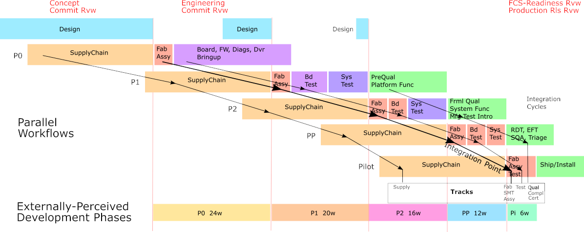
Development Tracks cut across these Integration Cycles using each Cycle to implement progression of intended Track content. Track content is defined as the sequence of functionality or operation shown as column content for major program participants, in the table below planning Function Alignment Sync Points. Content starts as initial prototypes in the first Cycle and progresses toward fully functional and configurable production customer shipment in late Cycles. Each Track defines its function to be realized in each Integration Cycle, aligned in agreement with all other Tracks as of a defined “Integration Point”.
Within each Integration Cycle an Integration Point is defined to quantify date of alignment or synchronization of functionality for the Integration Cycle. This is usually the start of the SMT solder step for hardware elements, which commits critical acquired material to the Integration Cycle without possibility of repudiation. This point sets the date within each Integration Cycle by which predecessor tasks and functionality to commit to SMT must be complete, and which drives the task sequence following for which their predecessor tasks and functionality must be complete.
The figure below illustrates Development Tracks likely to be included in a system development Program:
- Supply (Material acquisition or fab, initially local distribution; then procurement by local CM then production CM volume purchase then volume production and production supply agreements).
- CM (Contract Manufacturer) Protos initially local fab and CM with manual test, later to production fab and CM with test automation and assembly construction).
- Function alignment among product software and hardware elements as shown in the table farther below in this doc.
- Qual/Cert Test (Engineering bringup, PVT/Corner, pre-Qual, Formal Qual (environmental, ESD), Compliance (SQA, Environment, Safety), Certification (Security, Privacy).
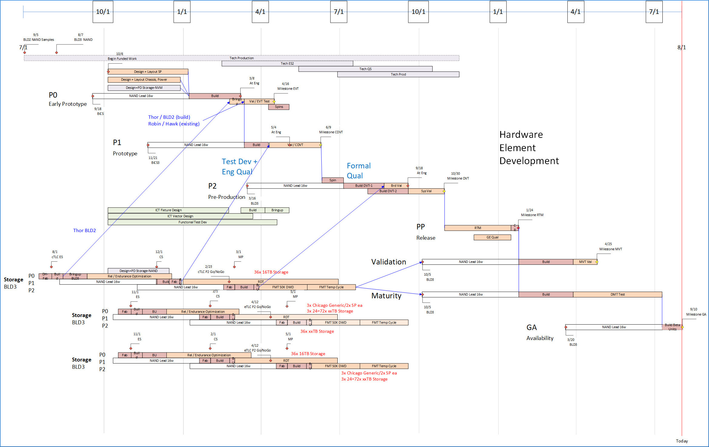
Hardware Phased Workflow, Detail
Below is shown the development sequence of a hardware system element in more realistic detail. The progression of Phases for the element shown is pretty clear. This element has a secondary board developed in parallel at bottom left, showing several strategy alternatives and decision points with illustration of how they affect overall schedule depending on feasibility. Typically a Program contains several elements, each consisting of board(s), several mechanical parts and assemblies, embedded power supplies, PCIe boards, and cables; and maybe FPGA or even chip development; and each such element would have a similar development sequence.
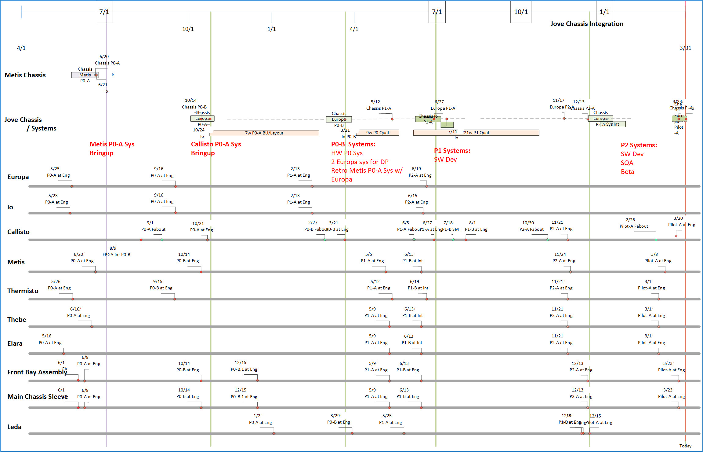
Integration
Among multiple elements there would be integration and test steps for each Phase to build assemblies, and from them, systems, to provision organizations such as Software, System Management, Manufacturing Test, customer Alpha testing, Training etc. Hardware and software are integrated at board level, assembly level and system level. Some of that will show in the System-level development plan coming up. The next visual shows how schedules are synchronized among multiple elements, for builds and integration. The lower part of the image shows the builds synchronized to feed the integration steps for each Phase, at assembly and system level in the task bars toward the top of the image.
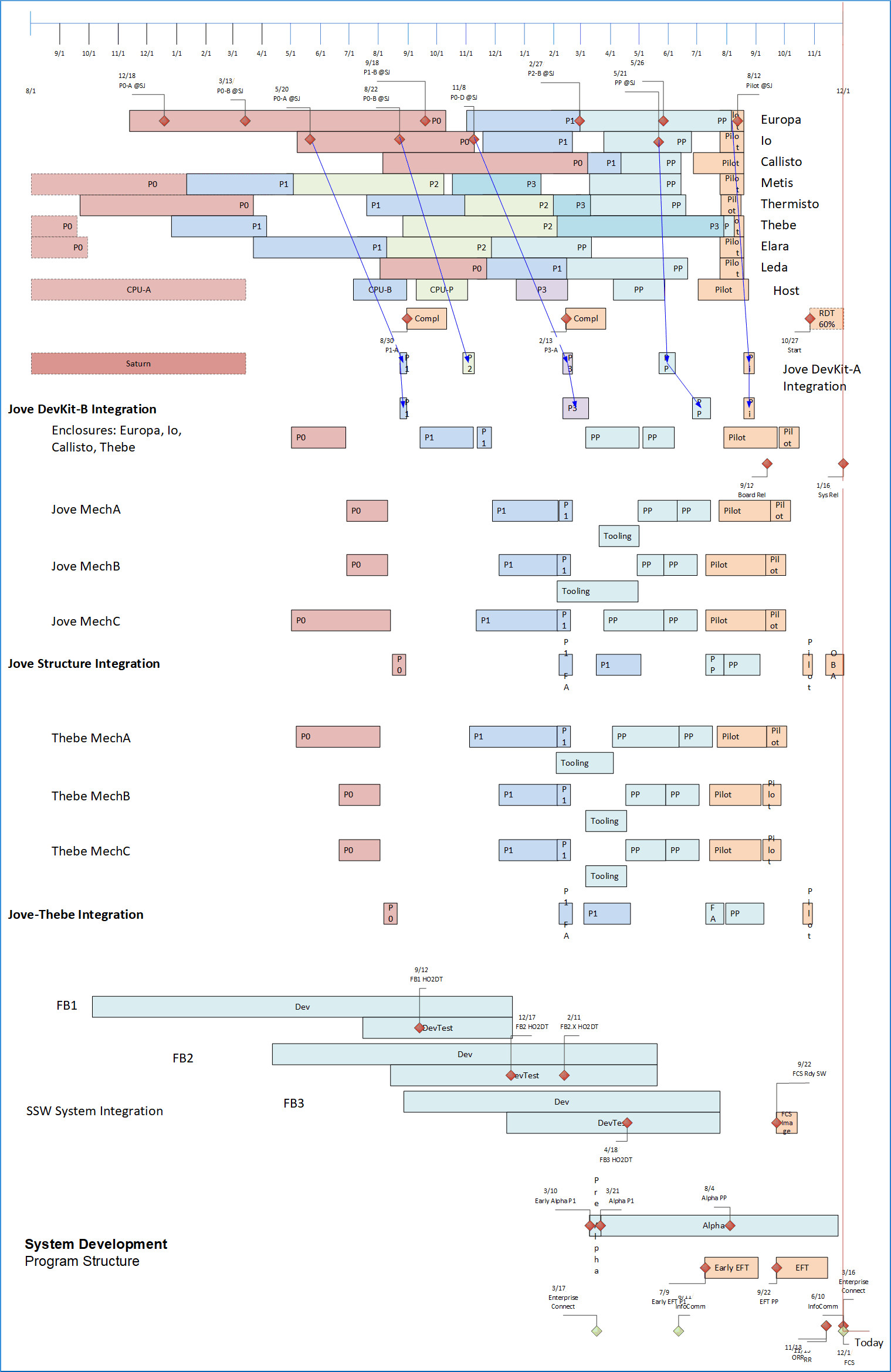
Full Project, Phased.
Below is shown how the elements of the full system are planned to come together. The block of electronic elements at the top represents assemblies of the type described just above on this page. The elements are illustrated in shorthand, showing only their critical path tasks, hiding the parallel tasks in each. Development of all the program elements is done in parallel of course. Also, if you look carefully, you can see how a big change is absorbed.
Just below that block of elements, are tasks integrating them with the mechanical assembly elements below them, and with the software Feature Blocks below that. More detail on the software elements follows below on this page. At the bottom of the figure is the program end game among all organizations and product elements, including final Compliance, Certification, SQA, internal Alpha and customer Beta test, and ultimately First Customer Ship (FCS).
The Program Plan, as stated, is quite adaptive, and updated continuously to synchronize dependencies and deliverables among all product elements, differing technologies, multiple organizations.
System Development Plan for Software
The elements portrayed above are driven by management of hardware physics. But software development methods differ from hardware, obviously. Some software elements, with limited inter-dependencies with the rest of the System platform, may be developed completely using Agile methodology, to be made available on the system platform. This brings with it all the advantages of development flexibility and responsiveness, although is somewhat harder to drive a functional grouping to meet a particular date for integration. At this level, there’s a requirement to avoid functional regression meaning that at FCS it must support the functionality and compatibility of prior-generation systems in use, while also supporting the System platform schedule. At lower levels, firmware, diagnostics, driver, and low-level system management are much more tightly tied to the System platform elements and development processes (bringup, engineering qual, compliance, manufacturing test), so their functionality availability closely parallels the hardware availability. They may also be developed as Agile, although oftentimes they are not. Net, dependencies and deliverables are loosely tied at higher architectural levels, and tightly tied at low levels.
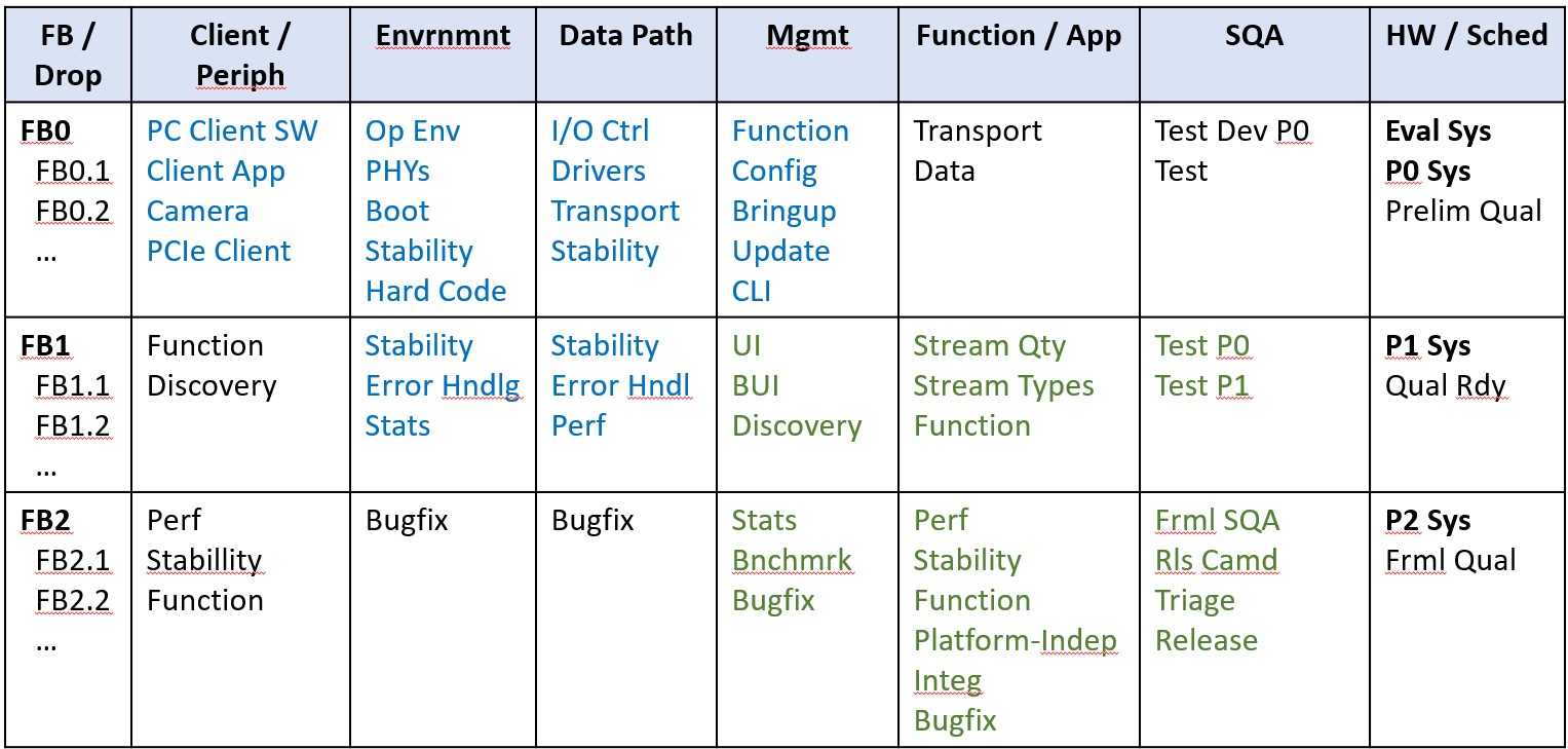
Function Alignment Sync Points for Agile and Phased elements. How are Feature Blocks (PIs) synchronized with the overall system development?
A table of Functionalities by type, horizontally, is shown below. Each type shows, vertically, a progression over time from more primitive- toward final-capability, with declining use of scaffolding as functionalities become available to cover dependencies. The collections of functionalities are grouped so that a “handful” of synchronization points can be identified; as shown, FB0/P0 distribution for initial bringup; FB1/P1 for full development and prep for final Qual; and FB2/P2 for formal Qual and initial customer Quals. These groupings sync function among all elements and organizations, including hardware, software, Ops et al. They would at minimum reflect synchronization across the program at Phase boundaries; and more could be defined by the Team wherever useful. Between sync points, each function must provide scaffolding needed until its dependencies can be satisfied. Minimizing the sync points allows maximum flexibility between them, enabling reasonable use of Agile methodology where desired.
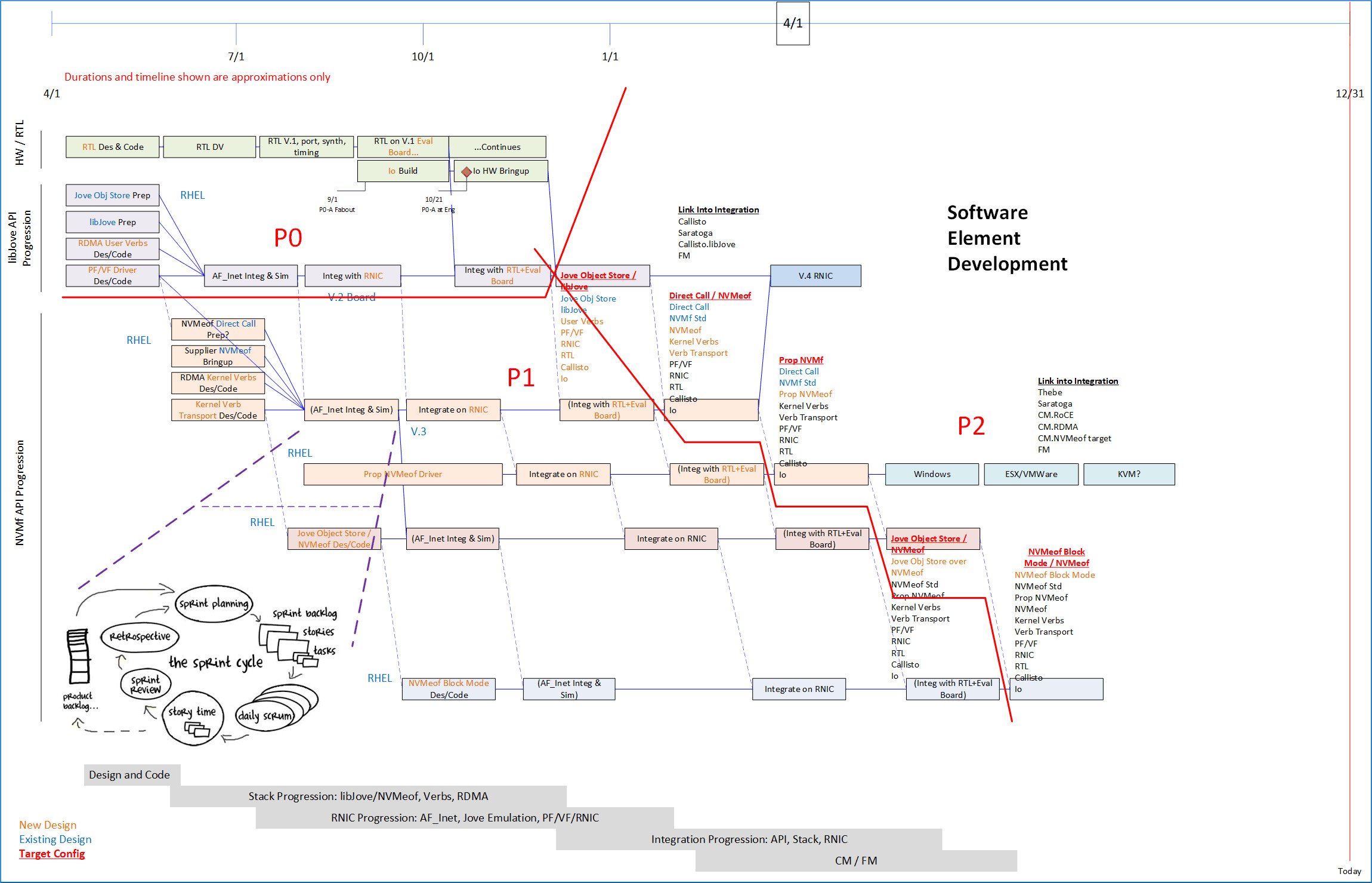
Software Sprint Workflow, Synchronized With Phased Elements, Detail: Sprint sequences for developed and acquired software elements, aligned with developed and acquired prototypes from hardware development phases.
Predicting and managing dependencies and deliverables usually (always, in my experience) helps development to flow. The following image shows sequences of Sprints, each developing a different functionality and API, scaffolded for initial development on third-party hardware, transport, and driver, then moving to Program-developed elements (adding value-add functionality of course), and finally on to work with various client environments. The red-lined areas correspond to functional development for FB0/P0, FB1/P1 and FB2/P2, which sync up with other system elements that use the module illustrated, to use functionality available within the red-outlined segments. This is low-level stuff somewhat tied to hardware scheduling, but still uses Sprint/Scrum/Backlog etc. methodology – so Almost-Agile.
So that’s what a project looks like, in my experience, with Phased and Agile methodologies working together to develop systems involving software and multiple hardware technologies. Key overall methodology includes synchronizing tasks and deliverables throughout the program, and designing, quantifying, and managing critical path continually. Without doubt it’s hard work, but it’s demonstrably possible to meet function, delivery and expense objectives – on plan! To make it practical and do-able to create such a synchronized plan and keep it evolving with reality, the plan itself has to be easily and continuously adaptable. And that’s where the Tools, Templates, and Methodology to be discussed in this series come in. More on that shortly.
Further Reading: Core Program Quantitative Structure for System Programs
Advice for Program Managers: The Blog Series
1-Program Management Opportunity
Introduces a vision and framework for development of Program Managers and PMO, for Program Management specialization to its environment, and for improved effectiveness and integration of PM with organization
operational management.
2-Program Management Career Path
Describes career path thinking for Program Managers including sourcing, progression, advancement, and connection with organizational management.
3-Program Management Career Skills
Career path thinking for Program Managers including skills and behaviors that develop Program Manager capabilities and leadership and pave the way toward advancement.
4-Program Management Specialization: System Programs Phased Methodology
PM Best Practices and Core Program Structure for Hybrid integrated system programs using Phased HW – Agile SW, mixed-technologies. Full-Program agility via automated plan tools with continuous plan update.
The Series also solicits contributions to this Blog site, to extend coverage of PM Best Practices and Core Program Structure to a broadening set of Specializations.
5-PMO Role
PMO behavior to achieve Program Management effectiveness specialized to its environment managing PM practices in the organization, including PM development and advancement and connection with organizational management.
6-Quantified Agile for Hardware
Program Quantification applied to Phased and Agile methodologies to deal with organizational quantitative requirements.
More Articles by this Author
Three Levels of Program Management
Guiding Principles for Program Management Action, Program Quantification, and Leverage Through Tooling.
Organizing Program Communication
Program Management depends on effective communication. Design Program communication paths for everyone throughout the Program.
Database Platforms for Program Management Logistics
Logistics Tool extended, using SQL Server and MS Access with MS Excel and PowerQuery.
PowerQuery Tool
Logistics Tool using MS Excel Power Query.
Quantitative Management
Tool methodology for agility with continuous plan update: Program BOM, Tie to Dates, Builds, Element data.
Complex Programs: Structure
Structure Program with Parallel Phasing. Describes coordination of EE/ME, FW, Test, Supply/CM, Driver/Kernel, Transport, Management. Scheduling, Integration points, scaffolding, and starting work. Hybrid Program Cross-Domain Coordination of dev frameworks, including Phased and Agile/Scrum where appropriate, via integration points and scaffolding. Software Integration Sequence and Dependency Planning.
Managing Complex Projects
Problem Statement. PM responsibility for Program Management drive throughout an organization, also includes schedule, budget, integration, critical path, logistics.
Program Roadmap
Planning work structure for a Program, and using the plan effectively.
Lifestyle AI
AI effects on current and future lifestyles. Personal strategies for proactive and defensive use of AI.
Iterative Thinking
Using Iterative Thinking to solve big problems and complex logistics.
AI Lifestyle Resources
AI resources to help adopt AI into your lifestyle.
PM/PMO and AI Best Practices
PM/PMO role identifying, evaluating, and propagating AI Best-Practices through an organization.
Framework Business
Development Frameworks directly affect business fundamentals of the organization.
PMO Positioning
Positioning PMO for better business results.
AI Unknown Unknowns
AI in the physical world.
Link To Free Tools To Manage Schedule, Logistics, And Finance
Author’s softtoyssoftware.com website with articles on Program Management and Program quantification tooling using Excel, MS Project, and MS Visio with SQL databases PowerQuery, SQL Server, and MS Access. Articles describe how you can use tools available from the website, or develop these capabilities yourself using commonly available tools.
Tools available from this website are free. They can handle small to large programs, limited only by your imagination. Using the included Program Template to envision, organize, plan, and run a large program puts me in mind of unleashing a Roman Legion to a sure outcome. Veni, Vidi, Vici! – Julius Caesar.
- https://www.softtoyssoftware.com/dbnet/programmingprojects/powerquerytool.htm
- Details on design of Structured Tables, JOINs, Reports/Pivots in Tools.
- Schedule, Visualization, Reporting.
- Hybrid program agility with continuous plan update.
- Microsoft 365 Desktop – based.
My Website: www.softtoyssoftware.com
Image(s) used under license from Shutterstock.com. Attribution: Peteri / Shutterstock.com
Diagram Images Copyright 2019 Richard M. Bixler
